
March 2008
|
Urgent Computing in Support of Space Shuttle Orbiter Reentry
|
 March 2008 |
On February 1, 2003, the Space Shuttle Orbiter Columbia suffered catastrophic structural failure during reentry, tragically killing all seven crewmembers on board. An extensive investigation into the accident was conducted in the ensuing months and identified that foam debris-induced damage to the reinforced-carbon-carbon wing, leading edge thermal protection system was the most probable root cause of the failure. During the course of the investigation, the Columbia Accident Investigation Board (CAIB) made a number of recommendations, which NASA agreed to implement before returning the Shuttle fleet to flight.
One of these recommendations, R3.8-2, addressed the need for computer models to evaluate thermal protection system damage that may result from debris impact. It reads:
Develop, validate, and maintain physics-based computer models to evaluate Thermal Protection System damage from debris impacts. These tools should provide realistic and timely estimates of any impact damage from possible debris from any source that may ultimately impact the Orbiter. Establish impact damage thresholds that trigger responsive corrective action, such as on-orbit inspection and repair, when indicated 1.
Implementing this recommendation was no small task, and involved hundreds of personnel from NASA, Boeing, The United Space Alliance, and other organizations. The result of this effort was the creation of a family of analysis tools that are used during the course of a Shuttle flight to assess the aerothermal, thermal, and structural impacts of a given damage site. These tools necessarily cross disciplines because, ultimately, the health of the vehicle depends on the coupled interaction of these three fields. The suite of tools spans the range of complexity from closed-form, analytical models to three-dimensional, chemical nonequilibrium Navier-Stokes simulation of geometrically complex configurations.
The focus of this article is to overview the damage assessment process, which is now a standard part of every Shuttle mission. The primary focus will be one aspect of this process, namely the rapid development of high-fidelity, aerothermal environments for a specific damage configuration using computational fluid dynamic (CFD) models 2 3. The application of such models requires immediate and reliable access to massively parallel computers and a high degree of automation in order to meet a very aggressive schedule. The remainder of this article is outlined as follows: Section 2 provides an overview of the damage assessment process and required timeline, Section 3 describes the role of high-performance computing in rapidly generating aerothermal environments and associated challenges, Section 4 details the specific example of damage that occurred on STS-118 during the summer of 2007, and Section 5 provides some observations and general conclusions, which may be applicable to any process which demands urgent computational simulation.
NASA and its commercial partners instituted a number of process and data-acquisition improvements during the two-and-a-half year lapse between the Columbia tragedy and Discovery’s historic return-to-flight mission. These improvements were specifically designed to identify and assess the severity of damage sustained to the thermal protection system during launch and on-orbit operations. The majority of such damage has historically been caused by foam or ice shed from the Orbiter/External Tank/Solid Rocket Booster ascent stack, but a limited amount of damage has also been attributed to micrometeor and orbital debris hypervelocity impacts.
A number of ground and air-based imagery assets provide video coverage of the vehicle’s ascent to orbit. These imagery data are intensely reviewed during the hours after launch to identify potential debris strike events. Multi-band radar assets are also deployed on land and at sea during the launch phase to identify any off-nominal signatures, which may be related to debris impact. Additionally, the wing-leading-edge structural subsystem of each Orbiter was instrumented with a suite of accelerometers to aid in the detection of potential debris strikes.
Once the vehicle is in orbit, there are additional procedures that are executed to help identify potential damage. On the second day of flight, two crewmembers perform a detailed scan of the reinforced-carbon-carbon wing leading edge and nose cap. This scan is specifically designed to detect very small damages that could potentially cascade into a catastrophic failure sequence during the extremely high temperatures of reentry.
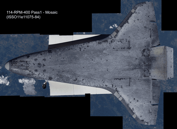
Prior to docking with the International Space Station on the third day of flight, the Orbiter executes a specific maneuver designed to aid in damage detection. The vehicle essentially performs a back flip while approximately 600 meters away from the Station. During this procedure two Station crewmembers perform photography of the vehicle. The imagery resolution is such that 7 cm damage can be identified anywhere on the vehicle, with damage as small as 2 cm identifiable in specific areas of interest. Imagery experts and hardware technicians provide the essential damage descriptions that are taken as input to a cross-disciplinary analysis. A composite lower-surface image that was obtained during Discovery’s return-to-flight is shown in Figure 1.
Each of the previously mentioned data acquisition tools is used on every mission. These data often provide the damage assessment team sufficient data to clear the vehicle for reentry. This is not always the case, however, and additional assets can be used to perform a focused inspection of a particular damage site that may be of concern. One such data set will be presented later.
It is at the end of flight day three when all of these data are available to analysts on the ground that the damage assessment process begins in earnest. From flight days three to five the coupled aerothermal-thermal-stress analysis process is performed for each identified damage site. The goal is to disposition each site as acceptable or unacceptable for reentry based on a set of well-defined structural and thermal limits. If a site is deemed unacceptable for reentry, it is the damage assessment team, in conjunction with on-orbit operations personnel, who work together to design, implement, and affect a repair procedure.
The first step in this process is to determine the aerothermal environment induced by a specific damage site. This includes any local changes in heat transfer that may result, as well as global effects such as early boundary-layer transition that may affect the downstream portion of the vehicle. Principally, empirically based correlations are applied to each site. These correlations are based on extensive test and analysis data that were performed pre-flight for physically relevant and geometrically similar conditions.4 As with any empirical correlation, however, questions of suitability for a particular case invariably arise and must be addressed. This is the primary area where high-fidelity analysis is used during the nominal process.
These aerothermal environments are then used as boundary conditions in transient thermal analysis for each site. The two primary goals of the thermal analysis are (i) to identify any material exceedances that may occur (e.g., exceeding allowable temperatures for aluminum structure), and (ii) to provide a damage-specific environment that can be used in stress analysis.
Assuming that a damage site has not exceeded material limits, the possibility still exists for local buckling due to thermal stress, for example. In this way the thermal environment is taken as input to a stress assessment that evaluates the potential for such effects. It is only when the end-to-end process is applied to a given site and presents no issues that the damage is deemed acceptable for reentry.
If the baseline process identifies an issue with any damage site, additional analysis is performed and the site is also considered as a candidate for on-orbit repair. It is in such high-risk scenarios that high-fidelity analysis and high-performance computing is particularly valuable.
The intent is that the pre-flight mission timeline occurs uninterrupted while this process is executed on the ground. The nominal damage assessment process is scripted and well-rehearsed as to fit in a nominally 24-hour timeline. This is absolutely essential to mission success. In this way any damage that may require repair is identified and reported to the Mission Management Team by no later than the fifth day of flight. It is at this point during the flight when the schedule for the remainder of the mission is finalized. In particular, if a repair must be executed, it must be identified at this point so that adequate resources (e.g., breathable oxygen, water, spacecraft power) can be allocated. Identifying a problem late in the mission may be useless as there may not be adequate resources available to affect a repair.
It is in this compressed timeline that high-fidelity analysis must be performed if it is to be of value to the overall process. Additionally, the data environment is highly dynamic, as new characterizations of a damage site are continuously acquired. The timeline is such that a high-fidelity analysis must have a turnaround time of approximately eight hours or less for it to be useful. This requirement poses a number of challenges.
The two primary CFD codes used by the reentry aerothermodynamic community at NASA are the LAURA and DPLR codes from Langley and Ames Research Centers, respectively. Both codes are block-structured, finite volume solvers that model the thermochemical nonequilibrium Navier-Stokes equations. LAURA 5 was originally written in Fortran 77 and was highly optimized for the vector supercomputers of the day. Subsequent modifications to the code have incorporated MPI for distributed-memory parallelism. DPLR 6, written in Fortran 90, is a relatively newer code and was designed from its inception to use MPI on distributed-memory architectures with cache-based commodity processors.
The Columbia supercomputer, installed and maintained by the NASA Advanced Supercomputing Division (NAS), is the primary resource used for these analyses. Columbia is composed of 20 SGI Altix nodes, each of which contains 512 Intel Itanium-2 processors. (Columbia was ranked 20th on the November 2007 Top 500 supercomputer ranking.) Prior to each launch, NAS personnel reserve one node for dedicated mission support and alert the user community that additional resources may be reallocated if necessary. Columbia is augmented with department-level cluster resources to provide redundancy (albeit at reduced capability) in case of emergency.
Institutional policies preclude major modification to either the software environment on the machines or the supporting network infrastructure in a “lockdown” period leading up to launch. This helps assure that resources are available and function as intended when called upon. This restriction prevents overzealous firewall modifications from precluding access to resources, to provide but one example.
High-fidelity analysis is engaged in earnest when a request is made from the Damage Assessment Team, which operates primarily at the Mission Control Center at Johnson Space Center in Houston, TX. A geometric description is provided to the analysis team that can be discretized into a computational grid. The analysis team has developed a number of rapid-turnaround, grid generation schemes based on both algebraic and partial-differential-equation techniques. In particular, Gridgen scripts have been created to model common types of damage scenarios (such as a cavity formed by debris impact or protruding gap filler). These technologies allow for high-quality, block-structured grids to be generated automatically in less than an hour.
The primary goal of these simulations is to determine the aerothermal environment induced by a given damage in relation to a reference, undamaged state. Accordingly, a number of simulations of the entire Orbiter have been pre-computed at relevant reentry conditions 7 8. These results are archived on a 7TB disk array at NAS and are mirrored across the agency for redundancy. These global solutions provide both a reference for undamaged configuration and a convenient starting point for local analysis. Due to the predominantly hyperbolic nature of the governing equations, many areas on the vehicle are amenable to a local analysis approach, which considers only the damage site in isolation with upstream boundary conditions imposed using solutions from the reference dataset. Consequently, the resulting grid (hence the computing time) is significantly smaller than a global simulation of the entire vehicle with the damage site. This approach has proved invaluable in reducing the turnaround time of obtaining high fidelity CFD solutions (see reference 2 for more details). These improvements have enabled the mission support teams to either compute more cases or use less computing resources.
In recent Shuttle missions, ground-based arc-jet experiments have been performed, for evaluating material performance. However, any ground test can at best approximate the real aerothermal environment because no facility can duplicate the extreme flight conditions during reentry. Increasingly, this high-fidelity analysis capability has been used to help characterize ground-based testing and provides an invaluable tool for comparing and contrasting the test and flight environments.
Finally, rigorous quality control procedures have been implemented that fit into the aggressive timeline. This is a critical component of any computational simulation that is used in engineering design, but its importance is elevated for situations that are critical for risk analysis. Specifically, in this context an erroneous solution can be worse than just a waste of resources – it can actually be dangerous because simulation data are often used to judge the relative risk of two scenarios. Erroneous data could possibly lead decision-makers to actually choose the riskier of the two options. For the case of aerothermal analysis, a number of quantitative quality-control steps have been instituted to avoid this scenario. For example, simulations performed at the same conditions using both LAURA and DPLR are used as a quality control check. Additionally, metrics for quantifying the iterative solver for grid convergence are computed as part of the solution process. Finally, a team member who was not involved in producing the result subjects each simulation to a predefined quality control process.
Our experience has pointed out the importance of direct communication channels between the analysis team and those who ultimately make decisions as a result of these analyses. As mentioned previously, the coordination between the aerothermal, thermal, and stress components of the damage assessment process occurs at Johnson Space Center in Houston. The individual analysts, however, are spread out on both coasts at Langley and Ames, and are therefore very much removed from the end-users of the data.
To address this communications gap we require that two members of the aerothermal CFD analysis team be present at Johnson Space Center throughout the damage assessment phase of the mission. Two individuals allow 24-hour coverage, which is essential for our application. These team members provide a critical liaison between the mission operations center and the analysts in the field. They essentially “speak the language” of the personnel performing the analysis and ensure that any known limitations or concerns are adequately presented to the larger damage assessment team. Additionally, the reverse communication channel is also satisfied, alerting the analysts to any additional data that may need to be incorporated into their high-fidelity simulation.
Equally important, we think, is that the analysts understand exactly how the data they are producing is used in the larger overall damage assessment process. We therefore require that each analyst observe the process first-hand before participating in a mission. This can be either through participating in a mission simulation or observing an actual mission on-site at the Johnson Space Center.
A piece of foam insulation broke off the Shuttle Endeavour during the ascent portion of the STS-118 mission in August 2007. The foam struck the thermal protection system tiles on the aft end of the windward surface of the vehicle. The impact caused a 7.5 cm long by 5 cm wide cavity that was discovered during the docking back-flip maneuver mentioned previously. Detailed imagery analysis was performed and indicated that the damage extended all the way through one of the affected 3 cm thick tiles.
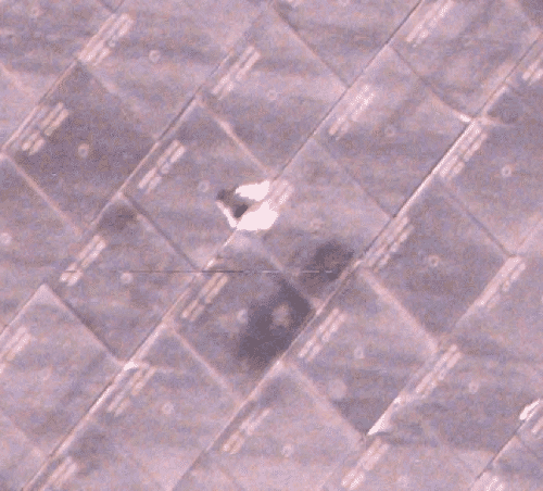
Figure 2 shows the actual image taken during the maneuver that served as the initial input to the damage assessment process. This damage was of immediate concern because it potentially exposed the sensitive tile bond line to the heat of reentry. The 6-inch square tiles are primarily composed of silica and are bonded to the underlying aluminum skin with a felt “strain isolation” pad. This arrangement allows the structure and tiles to expand separately when heated during reentry.
The damage configuration posed a number of potential problems that had to be addressed. The obvious question is whether or not this damage might allow a local structural burn-through and, if so, what the impacts would be. Additionally, since a portion of the insulating tile was removed, the bond line may overheat. This could allow the entire tile to be lost. Finally, increased local heating might cause excessive stress in the underlying aluminum skin due to thermal expansion.
Because of the potential severity of the damage, additional data were requested to help better characterize the damage. A detailed, three-dimensional scan of the damage was performed once the Orbiter was docked with the Space Station using Laser Doppler Range Imaging hardware. The data were downlinked to the damage assessment team in the form of a “point cloud” as shown in Figure 3.
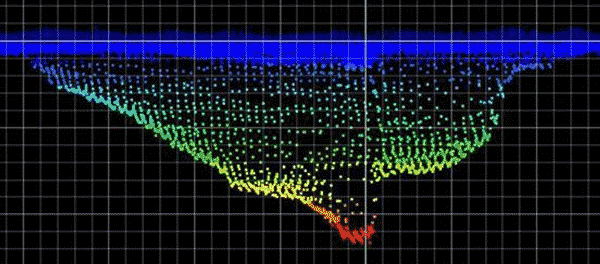
These data revealed that the cavity geometry was rather unique, and can be thought of as a cavity within a cavity. The deepest portion of the cavity extends to the insulation material between the two adjacent tiles. The neighboring tile is gouged roughly to the densified, lower portion of the tile. This configuration is fairly complex from an analysis point of view, and was somewhat out-of-family with the damages that had been used during experimental testing to develop a rapid-assessment, cavity-heating model. Consequently, the Orbiter Aerothermal CFD Team was asked to analyze the configuration to help provide the most accurate environment possible.
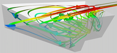
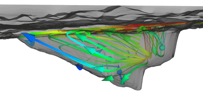
Due to initial uncertainty in the damage configuration, the analysis leads (at Johnson Space Center) requested that the analysis team (at Ames and Langley Research Centers) perform analysis on two different geometric configurations. Each configuration was analyzed at five different times along the predicted reentry trajectory. One of these configurations is shown on the left in Figure 4. The flow is from left to right, and the streamlines within the cavity are colored by temperature. The simulations showed that the majority of the high-energy flow bypassed the cavity altogether. Additionally, the critical exposed bond material was largely protected from the flow. The same set of streamlines is overlaid upon the scanned geometry and shown for reference in the right portion of the figure. The geometric similarity between the analyzed configuration and the true flight configuration is remarkable, and a unique capability offered by our urgent computing process put in place.
The initial results from the damage assessment process were promising, but questions still remained about the material response. An arc-jet test was designed specifically to address this concern. The scanned damage was machined directly into an existing, pre-instrumented tile array and tested in an approximate flight environment. Arc-jets are particularly well suited to this type of testing, but a key question is how the test conditions relate to the true flight conditions. The high-fidelity analysis process was able to help here as well by simulating the as-tested configuration.
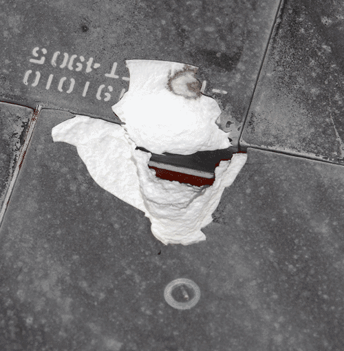
Based on the results of the complete aerothermal/thermal/stress analysis cycle, the decision was made to reenter the Orbiter as-is. The cavity is shown post-flight in Figure 5. It is clear from the figure that the damage did not progress during reentry. The correct decision was made.
It is worth mentioning, however, that a repair effort was being pursued in parallel to the nominal damage, assessment process. In the event a repair was warranted the urgent analysis process undoubtedly would have been engaged again to help assess and define repair requirements. This places a large burden on the analysis community, as they must carefully evaluate many possible scenarios. However, given the compressed timeline imposed by manned spaceflight with limited consumables, there is no alternative to this seeming chaotic, parallel-path approach.
The rapid aerothermal analysis capability put in place during NASA’s return-to-flight efforts has proven a, critical component of the damage assessment process which aims to assure the Shuttle is “go” for reentry. On multiple occasions, the Orbiter aerothermal analysis team has demonstrated the ability to meet the aggressive schedule demanded by real-time space operations support. In the case of STS-118, insights gained through this capability helped demonstrate that repair was not necessary, allowing the primary mission objectives to be achieved while ensuring crew safety. Given that Shuttle flights typically carry seven crewmembers, are estimated at $500 million a piece, and each Orbiter costs in excess of $1 billion, it is hard to underestimate the programmatic value of making the right decision in such circumstances.
Instituting this capability required the efforts of many people over a period of years. Key to its success was the dedication of these individuals and the tireless efforts of the overall team. The capability that has been put in place continues to evolve and benefits from experience gained each flight. We believe this is a critical aspect of using urgent computing to support high-stakes, real-time decisions. In our experience, it required three full-up system tests (in the form of pre-flight mission simulations) to effectively shake out the process, to illustrate strengths, and to identify and address weaknesses.
A highly automated process, robust quality control procedures, and dedicated, on-demand access to world-class resources are all prerequisites that help enable this capability. Equally important, and perhaps more surprisingly, are the human factors involved. Our experience is that timely generation of accurate results is critical, but proper interpretation and communication of those results is equally as critical. For our application, we require that analysis leads be co-located with the end users of the analysis data.